Top View
This topic describes how the Top View behaves in relation to your equipment when it is moving.
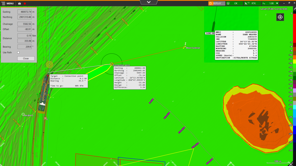
There are two ways to show your equipment in relation to your surroundings when it is moving:
-
Relative Motion - your equipment is shown as fixed and your surroundings move along the Top View.
-
True Motion - your surroundings are fixed and your equipment moves across the Top View.
On this page:
View Settings
To check or change the settings for the Top View screen:
 Right mouse click in Top View > View Settings
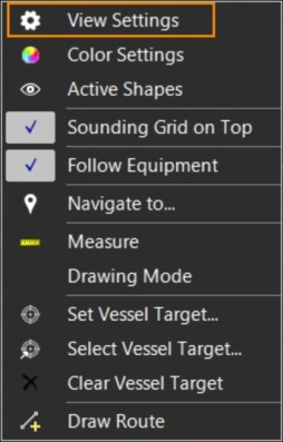
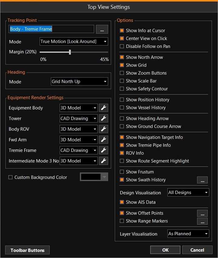
Enter settings for the looks of the items in the Top View.
The Options in the right hand panel will vary depending on the type of equipment in use and on the types of devices installed on board.
|
Top View Settings |
|
|---|---|
|
Tracking Point |
|
|
Selection box |
Use the browse button [...] to select an Offset Point as defined for this equipment in the Equipment Editor |
|
Mode |
Use the drop down menu to select how the screen should follow the equipment. |
|
Margin |
This value indicates how close your equipment can come to the edge of the viewing screen before it will be redrawn in the middle. Option not available for Mode: Relative Motion. |
|
Heading |
|
|
Mode |
Use the drop down menu to select how the screen should adjust itself around the equipment. |
|
Source |
Option available for Mode: Head |
|
Offset |
Option available for Modes: Head Up, Line Up and Custom Heading. How far offline from the Route |
|
Margin |
Option available for Mode: Head Up. The larger the Margin, the quicker a screen refresh is performed. Option not available for Mode: Relative Motion. |
|
Equipment Render Settings |
|
|
Select which type of drawing file to use: CAD
The various settings are identical to the ones used in the 3D View. |
|
|
Boom / FWD ROV |
Select which type of drawing file to use: CAD Drawing / 3D Model / Line / Outline / Hide. |
|
Custom Background Color |
Tick to activate. Select a color using the drop down menu. |
|
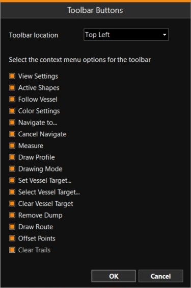
Add buttons to the view. This way you don't need to open the right-click context menu to carry out certain actions. The available options depend on your type of equipment and the installed devices.
When you tick the various menu options, they will appear in the toolbar at the location as indicated:
|
|
|
Options |
|
|
Show information at the location of your mouse, like position and levels. |
|
|
Center View on Click |
Wherever you click in the Top View with the left mouse button, this will be made the center of the Top View screen. If 'Follow Vessel' is active, and you click too close to the edge, the vessel will be placed in the middle again automatically. |
|
Disable Follow on Pan |
When you pan with the middle mouse button, 'Follow Vessel' will be automatically switched off when this option is activated. |
|
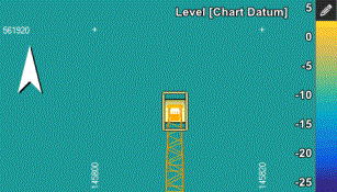
Show North Arrow |
A large North Arrow will be placed in the top left hand corner of the view window. |
|
Small crosses and chart coordinates will be shown in the view. |
|
|
Show Zoom Buttons |
Two large buttons will be added to the Top View. |
|
Show Scale Bar |
A Scale Bar will be shown in the lower right hand corner of the view. |
|
A contour is a line through points of the same height. The Safety Contour is an aid for safe navigation, indicating the boundaries at a height that is chosen by the Master. |
|
|
This is the track where the Origin of your equipment has passed. |
|
|
This option offers the possibility to mark the outline of your vessel during sailing or manoeuvering. |
|
|
This option is available for a Side Stone Dumping Vessel to generate traces for the active bays. |
|
|
Dredge Traces are markings to show where dredging has taken place. |
|
|
The heading arrow is an arrow in the direction of the heading of your Equipment. |
|
|
This is an arrow in the direction of movement over the ground at a chosen point on your equipment. |
|
|
Show Navigation Target Info |
When Navigate to (a Target in a Fix Set |
|
Chop Sticks are Ground Course Arrows attached to dredge heads. |
|
|
Show Frustum |
For use with a Swath Input device, or cable tracking with an Echoscope, the opening angle of the device can be visualized. |
|
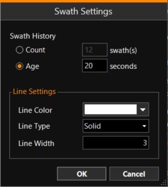
Show Swath History |
When using a Swath Input device, the track can be shown in the graphical area. Use the browse button [...] to enter the Swath Settings:
The maximum 'Age' to be shown is 20 seconds. |
|
For crane use only. Show the Range Circle of the current reach of the bucket. It can be configured in the Operation Settings. |
|
|
For crane use only. The Minimum and Maximum reach will be drawn as circles on the seabed. They can be configured in the Operation Settings. |
|
|
When the bucket is used to take fixes, you can show these in your view. Which point on the bucket is used to fix, is set in the Quick Access menu. |
|
|
Show all items as set in the Operation Settings. |
|
|
ROV Info |
When working with an ROV, show the related items. |
|
Indicate for which part of the Route the information (heading, offset, chainage, etc.) will be calculated. |
|
|
Design Visualisation |
A Design is the model or fixed level to which fill, excavation or dredging should take place. Use the drop down menu to select which Design to show: None - No Design will be shown. Active Design - Show only the Active Design. All Designs - Show all Designs available in your project. |
|
Show other vessels in your Top View, based on Automatic Identification System (AIS |
|
|
Show Excavation Line |
A box will be drawn around the head, indicating the area it will cover when dredging. The box allows for a clamshell shape |
|
The Offset Points are defined in VOSS.NET Equipment Editor when creating this piece of equipment. They can be shown in the viewing area. Click on the browse button [...] to the right.Select from the list which one(s) to show and fill in various settings for showing it/them in your screen. |
|
|
Range Markers are measurements between two points which can be visualized as a line and in numerics. |
|
|
Layer Visualization |
This option is only available for Flexible Fall Pipe Vessels and can be used when using a Box Installation Plan. This Plan can be created in the VOSS.NET - Box Installation tool. The Plan shows how much rock is to be placed per box. The Plan can be selected at Operation Settings - Main Shapes.
|
|
Design Visualisation |
Option available for, e.g., a Swath Input device.
|
|
OK |
Click to save all changed settings. |


|
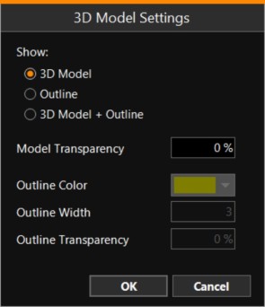
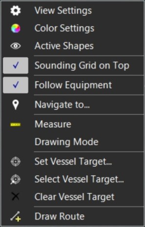
Top View Right Mouse Menu |
|
|---|---|
|
Color Mode: Level / Dredged / Difference /Slope / Lithology / None (and many others) - When Lithology is selected, only the top of the Voxel When None is selected, no grid model will be shown. |
|
|
Lists shapes which can be (de-)activated. Remember that this changes nothing in the Operation Settings, it only turns visibility on or off. |
|
|
Sounding Grid on Top |
Option only available when recording Multibeam data into a Sounding Grid. Select whether to draw the Sounding Grid or the Progress Grid on top. |
|
Follow Vessel (or Crane, Equipment, etc.)Vessel (or Crane, Equipment, etc.) |
When you turn Follow off, you can pan the view away from the equipment. |
|
Select where to navigate to. |
|
|
Cancel Navigate |
This option is only available when 'Navigate to', above, was activated. You can cancel that option here. |
|
Tool to get Easting/Northing and KP/Offset info of the target, as well as distance and bearing to the target (optionally via path). |
|
|
A support tool for online use, especially useful when discussing/explaining latest updated survey result with crew or identifying safe navigation options around the working area. |
|
|
A task bar will appear, ready to be used for drawing extra items in your screen. |
|
|
The outline of your vessel can be saved in the Top View, to mark that location to come back to, for example. |
|
|
In VOSS.NET, an Equipment Plan can be created before a project starts. This plan can contain Vessel Targets, to indicate where the vessel should position itself so it can carry out its work. When the Equipment Plan has been transferred to VOSS RT, the Targets will be listed when you select this option. Make sure you have the correct file selected in which they are stored: Menu>Operation Settings>Main Shapes>Equipment Plan. |
|
|
Clear Vessel Target |
The outline will remain in the Top View until 'Clear Vessel Target' is selected. |
|
Draw Route |
Draw a new Centerline When drawing graphically, the backspace button can be used to remove the last point. The options in the ‘New Route’ dialog allow the user to enter a name, adjust line settings and set the new route as Active Route. When not set as active route, the route is added to the Supporting Shapes. |
Tracking Point
The point on your equipment selected at Tracking Point will be kept in the middle when Relative Motion is chosen and will also be used to decide when a new screen should be built up when True Motion is used.
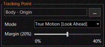
Mode
-
True Motion [Look Ahead] is designed for sailing forward.
-
True Motion [Look Around] is designed for maneuvering, where a screen refresh is performed all around your equipment.
-
Relative Motion - The equipment will be kept in the middle of the screen and the background will move around it.
Margin - The larger the Margin, the quicker a screen refresh is performed.
True Motion
If True Motion is chosen, your surroundings are being kept in one place, while your equipment moves across the Top View. When your equipment reaches the edge of the Top View, a new Top View will be built up. A large Margin % will perform a screen refresh more regularly. A 0 % Margin will only perform a screen refresh, when the Tracking Point reaches the very edge of the Top View.
True Motion [Look Ahead] will put your equipment on the opposite side of your sailing direction of the Top View, so you have a bigger screen area ahead of you.
True Motion [Look Around] will put your equipment in the middle of the screen, so you have screen area all around you.
Relative Motion
If Relative Motion is chosen, your equipment is being kept in one place while the surroundings move across the Top View. Your equipment is held in the middle of the Top View. If you zoom in a lot, you will notice that the point on your equipment that is chosen as Tracking Point will be held in the middle.
Follow Vessel (or Crane, Equipment, etc.)
Follow Vessel will always make sure your Vessel is visible in the Top View. If you want to inspect and zoom into some other area away from where your equipment is, you can un-tick the Follow option, and move around in your Top View by left mouse clicks, left, right, up and down keys and Zoom in / Zoom out.
Right mouse click in Top View > Follow Vessel
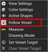
If the tick mark is visible, the Vessel is being Followed.
Center Top View around equipment
Independent of Relative or True Motion, Follow Vessel or not, you can always inspect your surroundings in the Top View by left mouse clicks, zooming or using the left, right, up, down buttons. When you do that, the Center Equipment symbol will appear in the top right side of your Top View:
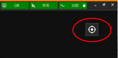
A left mouse click on this symbol will put your equipment back in the middle of the Top View, centering on the Tracking Point.
The Top View Tracking Point is set in the View Settings menu of the Top View.(See paragraph at top of page.)