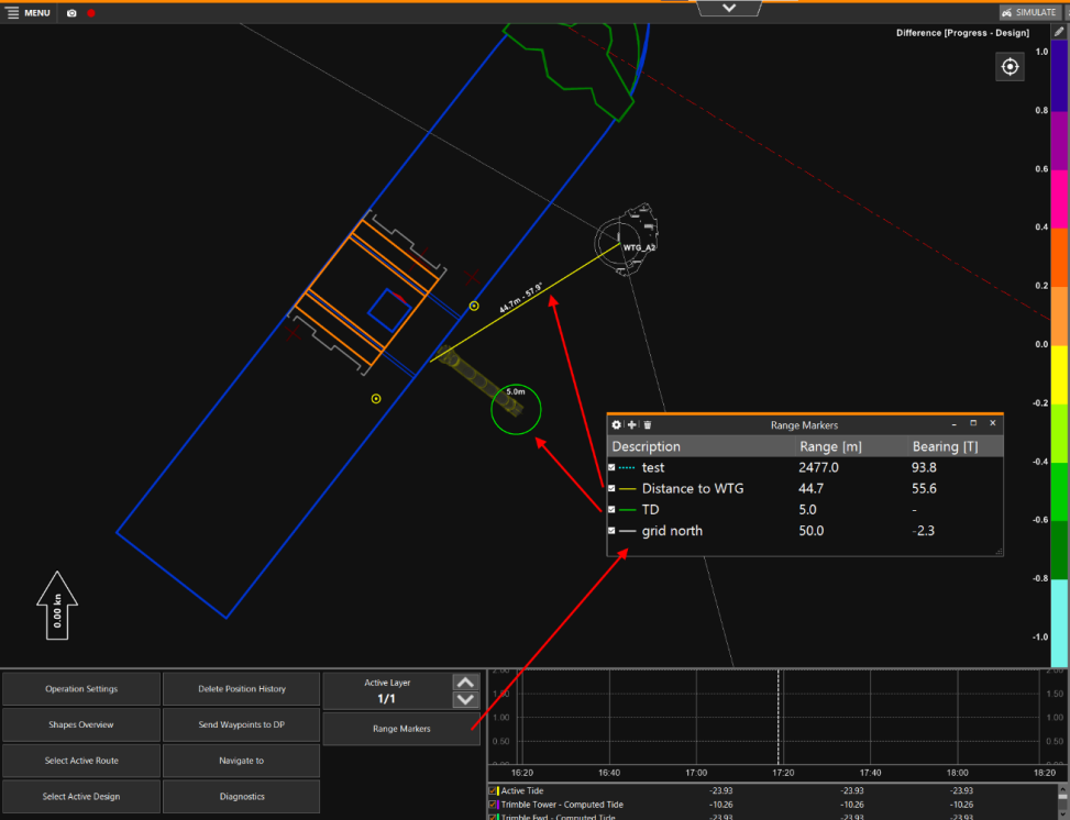
Range Markers
On this page:
Range Markers are measurements between two points (or a point with a radius) which can be visualized as a line and in numerics.
They can be added to your Top View.
Operation Settings
 Operation Settings > General > Range Markers
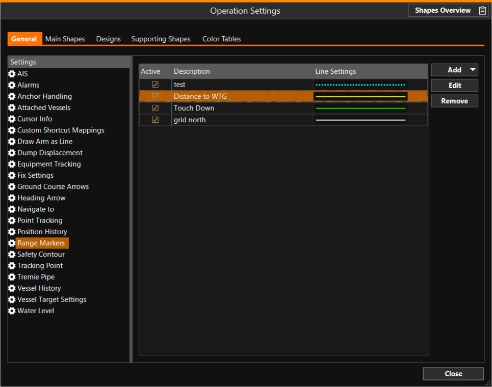
Click on 'Add' to add a marker.
There are two types of range markers:
-
Point
 A point consists of an Easting, Northing and Elevation. to Point - Line between two points, the range and bearing will be calculated.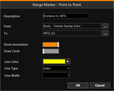
Select the From and To position from a list of targets.
-
Point with Circle - Shows a circle around a point.
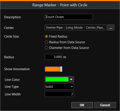
Select the center of the circle from a list of targets and the radius/diameter.
The radius can be fixed or from any value source from the equipment (like a computation or device).
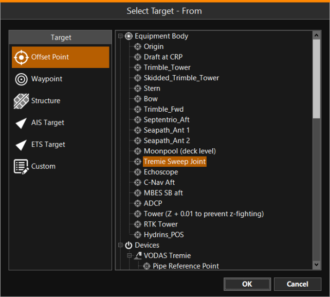
Select Target - From
The From/To positions can be selected form various sources:
Offset Points on the vessel, Waypoints Set of coordinates that identify a point in physical space. Waypoints for navigational use are usually defined in two dimensions (e.g. latitude, longitude, or Easting, Northing), Structures A Structures file is a Shape which contains a number of Objects, Model-definitions and Status-definitions, AIS Automatic Identification System - is comprised of small transponders fitted to shipping vessels worldwide, which use short wave VHF radio signals to broadcast each vessel’s position, unique International Maritime Organisation (IMO) identity number and other useful information. The transmissions can be received by any vessel, land station or satellite in range and fitted with an AIS receiver. and ETS Equipment Tracking System - can be compared to AIS, to show surrounding vessels or equipment targets, Custom positions or entities from shapes A geometric entity or a collection of such entities. Each entity is described by basic geometry such as a point, a line or an arc. Examples of shapes are: Route, Centerline, Waypoints, Fix Set, Dump Boxes, Progress Grid Model, Designs, etc. like Fix Sets, Dump Boxes, Structures, etc.
Each range marker has its own line settings and an option to show an annotation with range and bearing information.
Top View Settings
In each Top View, the active range markers can be shown or hidden.
Right-click in the Top View to open its Settings menu.
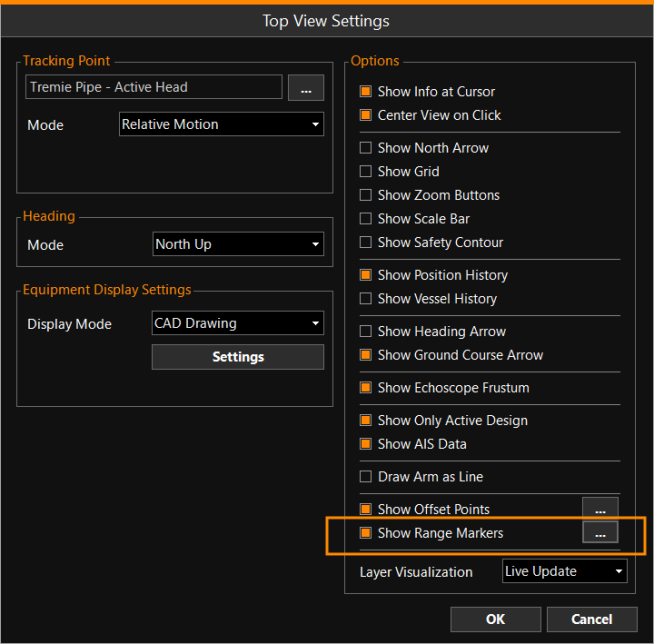
Click on the browse button [...] to select which markers to show:
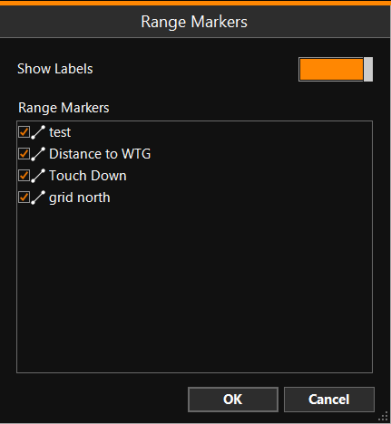
Tick the markers you want to see in your screen.
Show Labels - The markers will have an annotation right next to them.
Dockable Menu
To set this up, go through the following series of options:
MENU > Screen Layout > Add View > All > Dockable Menu > Add
This will open an empty Menu page.
Right-click in it to open the View Settings menu, then follow this series of options:
Edit Items > Additional Settings >
Range Markers >  > OK
> OK
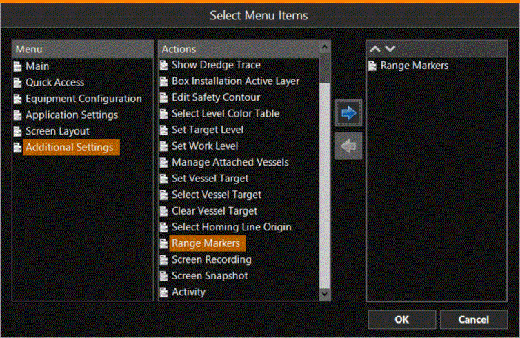
The created button will lead directly to the Range Markers window when clicked on:
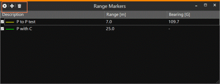
Double-click on a marker to edit it.
Tick or un-tick to disable a marker.
The top left hand corner shows a menu bar, where the Range Marker Settings can be adjusted:
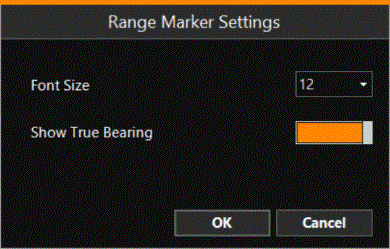
Show True Bearing - When activated, the True Bearing will be shown in the annotation. The Grid A type of DTM that is made manageable through sampling measured points into a regularly spaced raster, allowing fast and conditional access. Considered to be a secondary data set; since no original points are kept.. bearing is the default setting.
The marker information (Range/Bearing) can also be added to a Numerics displays.
Top View with activated Range Markers: