Designs
A Design is the model or fixed level to which fill, excavation or dredging should take place.
VOSS RT can contain and display various designs, however, only one design can be the Active Design.
On this page:
List of Designs
The list of available Designs for your operation can be found under Operational Settings:
 MENU > Operation
Settings > Designs or:
MENU > Operation
Settings > Designs or:
Keyboard: F1 >
Designs
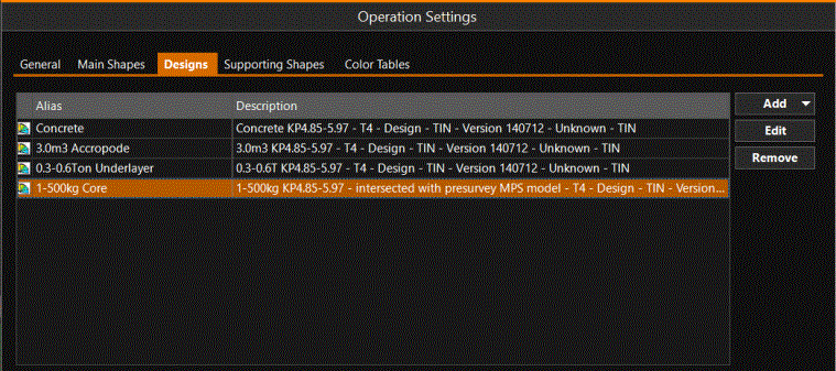
A list of Designs is shown that can be used as Active Design.
Add Design
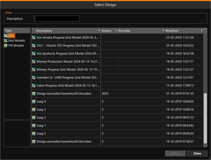
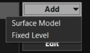
More Designs can be added to the list using the Add button. Select either a Surface Model A special type of shape. It is a digital representation of a 3D surface. The used types of Surface models are: Grid Model / Point Cloud / TIN Model / Soil Layer. or a Fixed Level.
For Surface Model: Using the browse button [...]
will show the Designs that are available in the SDM Survey Data Manager - the database that manages and carries the total set of your data..
If the one you need is not in the list, you should obtain it from the Surveyor via a Transfer Package.
Apart from Surface Models for Designs, you can also define a Fixed Level:
Enter the level, its Display Settings and its Tolerance Levels if necessary:
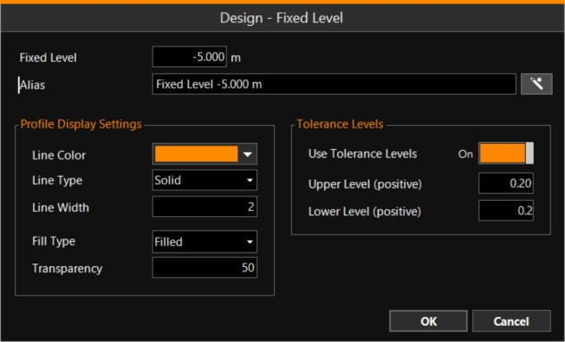
Click OK to save the Fixed Level.
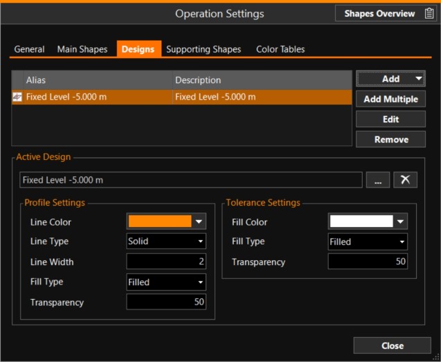
Tolerance Settings - The tolerances as entered in the previous window will be shown in the color and type as entered here.
Edit Design
Here, adding a Surface Model is explained.
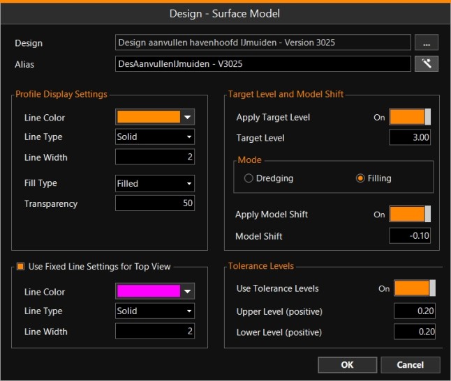
Design Name
Use the browse button [...] to select the correct model.
The name of the Design is shown, in the picture above 'Design aanvullen havenhoofd IJmuiden - Version 3025', which can not be changed.
You can give a design a more simple name yourself: the Alias. Create a clear Alias, as this name will be shown when you want to change the Active Design.
Click on the magic wand button for a suggestion for the Alias: 
Profile Display Settings
It is possible to set a line color/type/width for the profile. You can also select how to fill the space above or below the profile and whether this should be transparent, so other items in the view are still visible.
Use Fixed Line Settings for Top View
The color of TIN Triangulated Irregular Network - a vector based data structure that describes a surface, made up of irregularly distributed 3D nodes that define constraints. model constraints in top views is the same as in the Shape A geometric entity or a collection of such entities. Each entity is described by basic geometry such as a point, a line or an arc. Examples of shapes are: Route, Centerline, Waypoints, Fix Set, Dump Boxes, Progress Grid Model, Designs, etc./TIN Editor. Depending on the colors of the points, the constraints can have all kinds of colors, making it confusing for users of RT. It is possible to set a fixed line color/width/type for TIN model constraints for uniformity.
This same settings menu is available at: Operation Settings - Supporting Shapes - TIN Model - Edit.
Target Level
For each design a Target Level can be specified. A Target Level can be useful when filling or dredging is undertaken in various phases.
Be careful with the use of Target Levels, it should be discussed with the Superintendent and it should be mentioned during handovers of shifts!
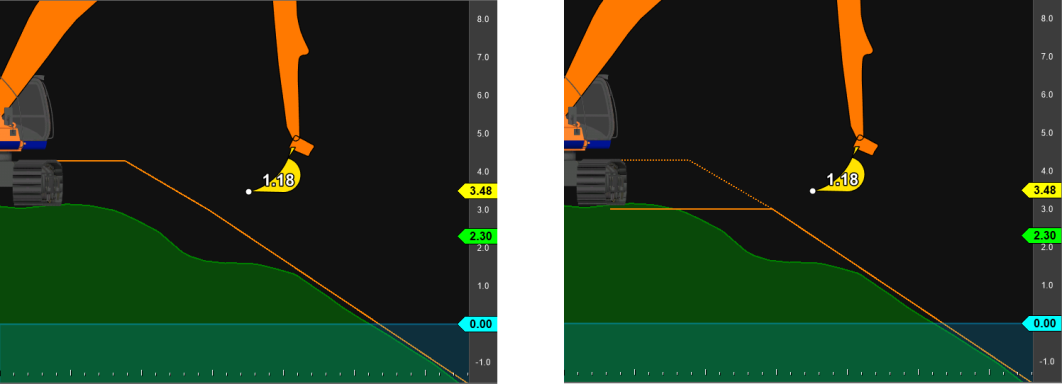
In the example below, on the left side, no Target Level is specified and the full Design is shown.
On the right side a Target Level of +3 meters with Mode 'Filling' is specified: anywhere where the Design is higher than +3 meters, +3 meters is presented. The original Design is also visible as dotted line.
Model Shift
For each design a Model Shift can be specified. The decision to use a Model Shift can be based on one or various surveys. If the equipment is well calibrated and on average still a difference to design exists, it could be decided to raise or lower the whole design vertically.
Be careful with the use of Model Shifts, it should be discussed with the Superintendent and it should be mentioned during handovers of shifts!.
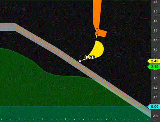
In the picture above, a Model Shift of -0.10 meter is used.
The original design is also visible as a dotted line.
Tolerance Levels
Tolerances on a Design can be specified per Design. They will be visible in Profile Views.
To be able to use them, switch them on. The values of Upper and Lower tolerance must both be positive and are always applied vertically with respect to the Design.
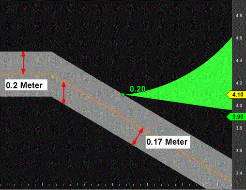
The Upper and Lower tolerance are visible in the profile views.
Note that due to that fact the tolerances are being applied vertically,
The thickness of the tolerance measured perpendicular to the design, is different on a flat surface than on a slope!
Only the tolerances of the Active Design will be shown. The way the Tolerances are presented (like their color) is specified at Tolerance Settings at: Active Design Profile settings and Tolerance settings
Make a Design Active
MENU > Quick Access
> Select Active Design
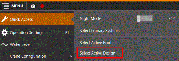
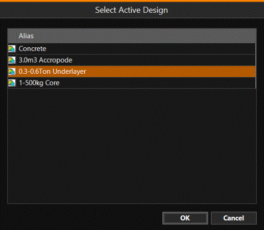
Click on the Design you want to make Active and click OK.
The Alias names of the Designs are shown. If you want to Add, Remove or adapt the settings of a Design, see top: List of Designs
If you want to change the way the Active Design is shown, see below: Active Design Profile settings and Tolerance settings
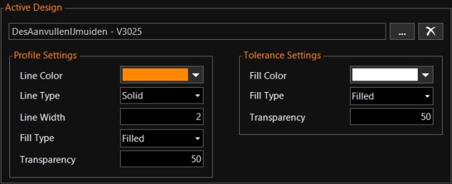
Active Design Profile settings and Tolerance settings
To change the way the Active Design is shown:
MENU > Operation
Settings > Designs or:
Keyboard: F1 >
Designs
At the bottom of the Designs menu, the way the Active Design is shown in profiles or in tolerances can be changed.
Note that the values of upper and lower tolerances must be specified at the design itself. See at top: List of Designs
Height above Design Settings
When using a Back View this setting will have effect.
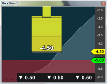
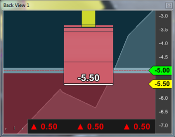
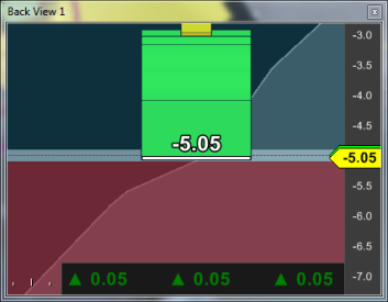
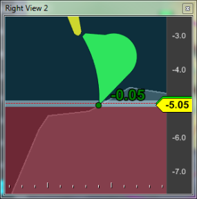
The images below show situations where the system indicates to the operator to drop or raise the bucket. In this example the tolerance is +/-0.10m, so the indicator swaps to green when the tolerance is met. The colored numeric indicators on the bucket are also present in a Right View. Tolerance settings themselves are related to the design and are to be found on the Operation Settings - Designs page - Tolerance Levels. See the images below for what happens in the Back View working on a design level of -5.00m.
In the 3D View the active head will change color accordingly.
Set Work Level
Creating a temporary design work level can also be done with a single click.
Make sure your mouse pointer is located inside a Dockable Menu. Now right-click inside this view.
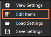
Right-click > Edit Items > Additional Settings > Set Work Level:
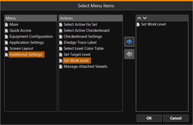
Use the blue arrow to move the option to the right hand column and click OK to return to the main screen.
The option ‘Set Work Level’ will be added as a dockable button. Clicking the button allows you to set a temporary fixed level design:
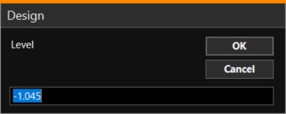
The height can be entered manually, but the default will be taken from the current height of the used tool (bucket, grab, etc.).