3D View
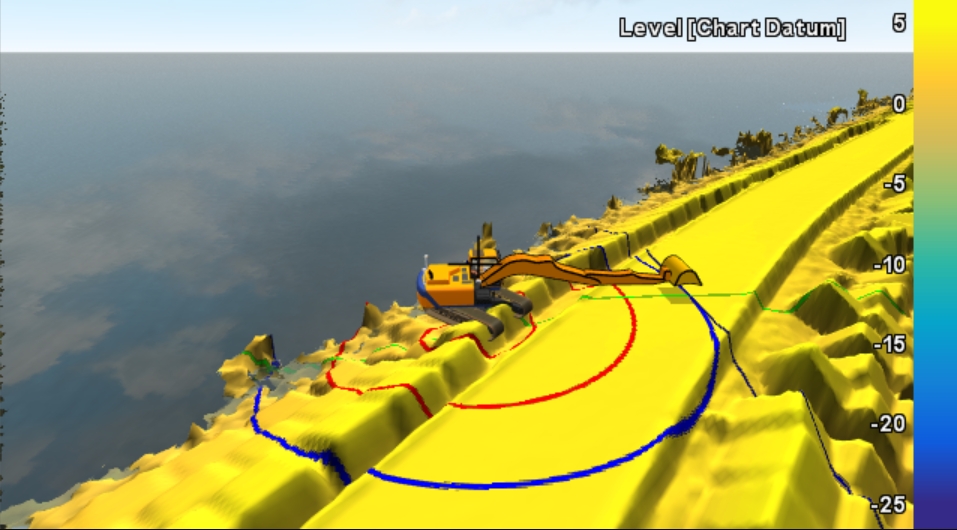
The 3D View is the most truthful representation of the equipment.
On this page:
View Settings
To check or change the settings for the 3D View screen:
 Right mouse click in3D View > View Settings
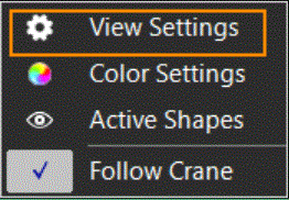
Enter settings for the looks of the items in the 3D View.
|
View Settings |
|
|---|---|
|
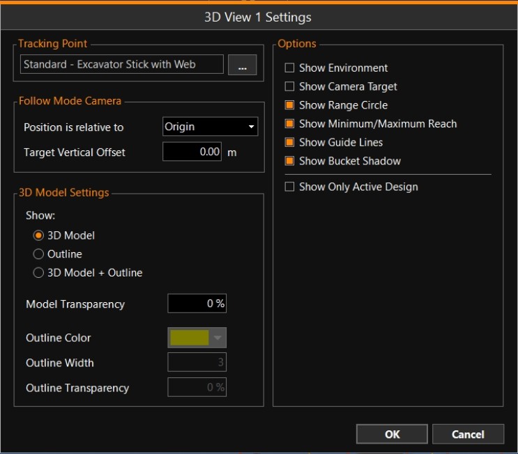
Tracking Point |
|
|
Selection box |
Use the browse button [...] to select an Offset Point as defined for this equipment in the Equipment Editor |
|
Follow Mode Camera |
The tracking point is kept in the middle of the view |
|
Position is relative to |
This changes the perspective on the equipment and surrounds.This point is the center of your view screen and will be shown by a white cross. |
|
Target Vertical Offset |
Enter a value if necessary. |
|
Show |
|
|
Model Transparency |
Only available when an option with 3D Model was activated above. Make the Transparency value larger to see the data underneath the equipment. |
|
Outline Color |
Only available when an option with Outline was activated above. Select a color in which to show the outline. |
|
Outline Width |
Only available when an option with Outline was activated above. Enter a width for the outline. |
|
Outline Transparency |
Only available when Outline was activated above. Make the Transparency value larger to see the data underneath the equipment. |
|
Options |
|
|
Show Environment |
Shows the water surface and the sky in a natural way. |
|
Show Camera Target |
Indicates the center which the camera is focused on, with a white cross. |
|
For crane use only. Show the Range Circle of the current reach of the bucket.It can be configured in the Operation Settings. |
|
|
For crane use only. The Minimum and Maximum reach will be drawn as circles on the seabed.They can be configured in the Operation Settings. |
|
|
For crane use only. Guide Line settings can be configured in the Operation Settings.Guide lines are only selectable in 3D View. |
|
|
Show Bucket Shadow |
For crane use only. Shows a footprint of the active bucket head. |
|
A Design is the model or fixed level to which fill, excavation or dredgingshould take place. |
|
|
OK |
Click to save all changed settings. |
|
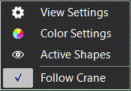
3D View Right Mouse Menu |
|
|---|---|
|
Color Mode: Select Level / Difference / Lithology (if a Voxel |
|
|
Lists shapes |
|
|
Turning Follow off, you are able to track mouse clicks.See paragraph below. |
FollowVessel (or Crane, etc.)
Follow Vessel will always make sure your Vessel/Equipment In VOSS RT Equipment is the collective name for all marine and land machinery provided with positioning (and attitude devices). is visible in the 3DView.If you want to inspect and zoom into some other area away from whereyour equipment is, you can un-tick the Follow option, and move aroundin your 3D View by left mouse clicks, left, right, up and down keys andZoomin / Zoom out.
Right mouse click in3D View > Follow Vessel
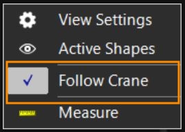
If the tick mark is visible, the Vessel is being Followed.