Screen Layout
The appearance of the view windows within your screen can be managed here:
 MENU > Screen Layout
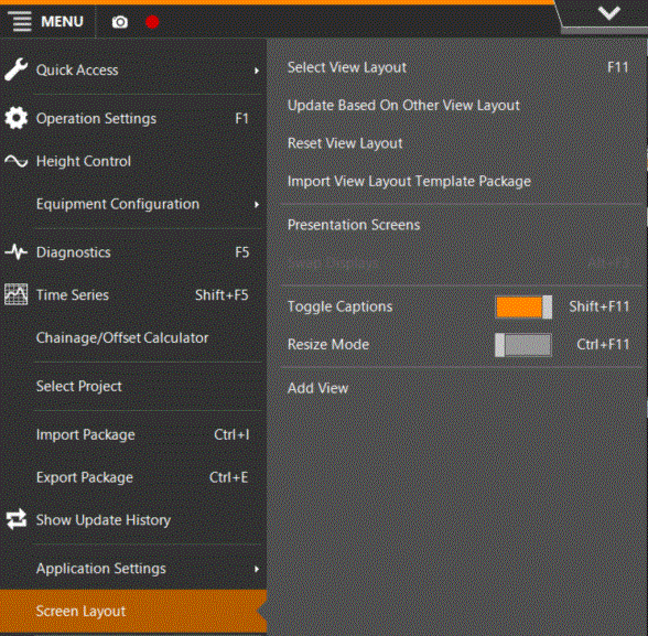
Settings to enter or adjust are:
Select View Layout
View Layout Templates are pre-defined and can be selected here from your SDM Survey Data Manager - the database that manages and carries the total set of your data..
Update Based on Other View Layout
Implement the views from another View Layout into your current View Layout.
Reset View Layout
Re-store the previous View Layout or go back even more steps of changes in the View Layout.
Import View Layout Template Package
An external editor can be used to create View Layouts, which can then be imported here.
The policy is that View Layouts can only be created by system administrators in order to keep the equipment layout uniform.
Presentation Screens
On a workstation with multiple displays, you can add one or more Presentation Screens to extend the application.
A Presentation Screen has the same menu options as the primary screen.
It can be activated or de-activated via the Show and Hide options in the Presentation Screens menu:
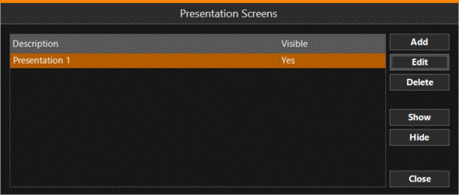
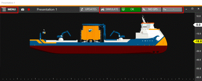
Click 'Edit' to manage the looks of the Presentation screen:
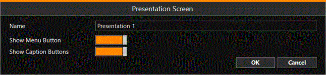
Switching off the main Menu Button and/or the Caption Buttons can be useful when presenting an uncluttered image to the client.
Swap Displays
When various displays are active, click on this option, or use the Alt+F3 button combination to swap the views from one screen to the other.
When only one screen is active, this option is grayed out.
Toggle Captions
This tool can be used to arrange the Screen Layout.
With Toggle Captions turned on, the names of the views are displayed on the tab in the top left corner:

When adding a new View, the Toggle Captions help you to dock the view into the desired location.
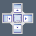
Grab the caption and drag it around with the mouse, using the item below to place it in its new location:
To de-activate a view, you first need to turn on Toggle Captions; on the tab in the top right corner a view can be removed by clicking the cross.
Normally, when working, this attribute can be turned off in order to use the monitor space as economically as possible.
Resize Mode
In Resize Mode, the window frames become bold, which makes it easier to grab and shift the frames.
By switching off this mode again, the settings are saved.
Normally, when working, this attribute can be turned off in order to use the monitor space as economically as possible.
Add View
A series of views are available in order to get control over the process in the best way.
All views have a context menu, which can be opened by using a right mouse click.
Margins in the context menus have effect on how strictly the view settings are followed up.
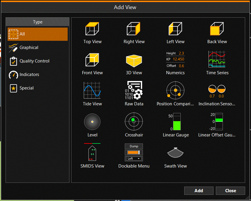
Viewing displays which can be added are:
Some items have not yet been explained completely. Do you happen to know what they are used for and do you have nice screen captures with realistic values entered? Please let the Documentalist know, she would be happy with your input.
Back View / Front View
Back View displays only the active arm and head. Showing the body can lead to contradictory graphics.
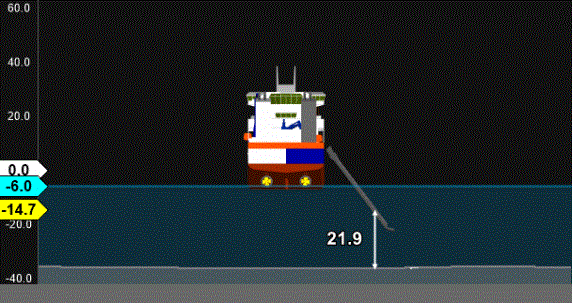
The Height Above Design parameters can be modified in the Operation Settings.
|
|
|
|
View Settings
|
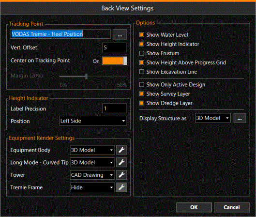
Tracking Point Vertical Offset - Enter a value if necessary. Center on Tracking Point - On / Off (only has effect in Follow mode). Height Indicator Label Precision - Define the number of decimals on the indicator sliders. Position - Define on which side of the display the indicator sliders will be positioned. Equipment Options - Select the various layers and levels to be shown in the display. If you don’t want to see the Dredge and Survey layers in Front and Back views and are only interested in the actual data, then the dotted lines that represent these layers can be switched off. Display Structure as - Structures |
|
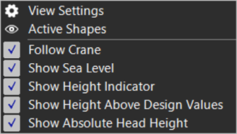
Lists shapes and can be (de-)activated, remember this changes nothing to the Operation Settings, it only turns visibility on or off. |
|
|
Follow |
Turning Follow off, you are able to track mouse clicks. The choice of the Tracking Point defines how the equipment is centered. |
|
Show Sea Level |
Actual Sea Level from source defined in Height Control /Tide Control. |
|
Height Indicators |
Sliders represent current elevations of origin (white) / head (yellow) / waterline (blue) / design level (green). |
|
Height above Design Value |
Numeric indicator representing the height of the head relative to the design. This value appears only when zoomed in on the head. |
|
Show Absolute Head |
Numeric indicator of the current head elevation. |
Raw Data
When there is interest in a certain value for continuous monitoring, a Raw Data View can be opened.
This view is similar to the Diagnostics window in Advanced mode. This view has no context menu.
Inclination Sensor
A collection of all configured inclination sensors in one overview.
|
|
|
|
View Settings |
Adjustable range and optional time series |

Level
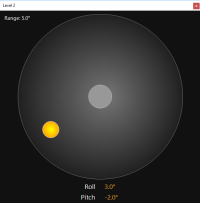
A dual axis spirit level display is a simple but effective representation of the equipment's attitude .
|
|
|
|
View Settings |
Adjustable range |
Linear Gauge
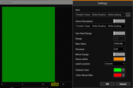
This screen can be used for visual quality control.