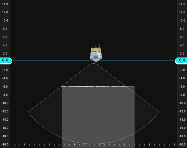
Swath View
Only when you have a Multibeam Echosounder installed will this option be available.
On this page:
View Settings
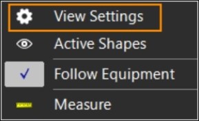
To check or change the settings for the Swath View screen:
 Right mouse click in the
Swath View > View Settings
Right mouse click in the
Swath View > View Settings
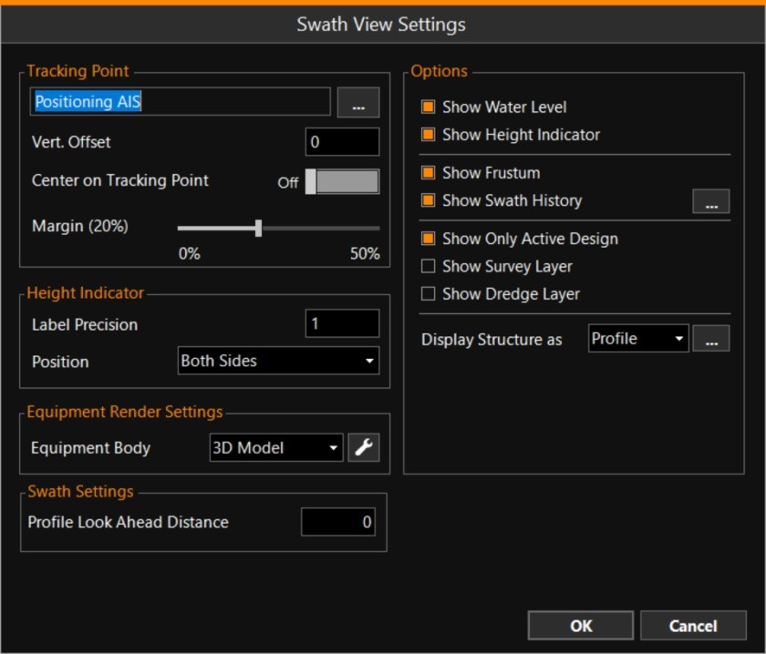
Enter settings for the looks of the items in the Swath View.
|
Swath View Settings |
|
|---|---|
|
Tracking Point |
|
|
Selection box |
Use the browse button [...] to select an Offset Point as defined for this equipment in the Equipment Editor |
|
Vertical Offset |
Enter a value if necessary. |
|
Center on Tracking Point |
Only has effect in Follow mode. The point on your equipment selected at Tracking Point will be kept in the middle and will also be used to decide when a new screen should be built up. |
|
Margin |
This value indicates how close your equipment can come to the edge of the viewing screen before it will be redrawn in the middle. Option only available when 'Center on Tracking Point' above is Off. |
|
Height Indicator |
|
|
Label Precision |
Defines the number of decimals of the indicator sliders. Enter a different value if necessary. |
|
Position |
Use the drop down menu to select on which side of the screen the colored Height Indicators should be shown. |
|
Equipment |
|
|
Select which type of drawing file to use: 3D Model / CAD
The various settings are identical to the ones used in the 3D View. |
|
|
Swath Settings |
|
|
Profile Look Ahead Distance |
A Progress Grid This option is useful in areas with slopes, so you can adjust the settings of your multibeam echosounder beforehand. If necessary, enter a distance in meters. |
|
Options |
|
|
Show Water Level |
Actual Water Level from source defined in Height Control /Tide Control. |
|
Show Height Indicator |
Sliders represent current elevations of Origin (white) / Head |
|
Show Frustum |
The opening angle of the multibeam echosounder can be visualized. |
|
Show Swath History |
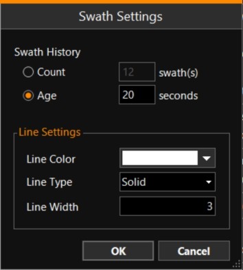
A series of swaths can be shown. Use the browse button [...] to enter the Swath Settings:
The maximum 'Age' to be shown is 20 seconds. |
|
A Design is the model or fixed level to which fill, excavation or dredging should take place. |
|
|
Show Survey Layer |
If you don’t want to see the Survey layer and are only interested in the actual data, then the dotted line that represents this layer can be switched off. |
|
Show Dredge Layer |
If you don’t want to see the Dredge layer and are only interested in the actual data, then the dotted line that represents this layer can be switched off. |
|
Display Structure as |
Structures |
|
OK |
Click to save all changed settings. |

|
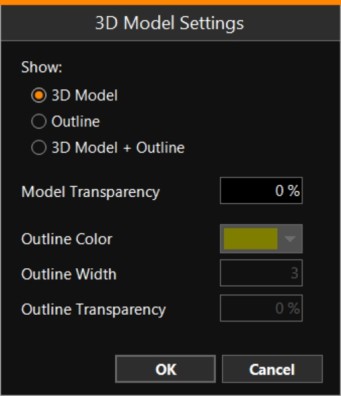
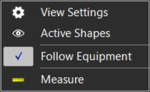
Swath View Right Mouse Menu |
|
|---|---|
|
Lists shapes |
|
|
Turning Follow off, you are able to track mouse clicks. See paragraph below. |
|
|
Tool to measure distance and bearing between two points. |
Follow Vessel (or Crane, Equipment, etc.)
Follow Vessel will always make sure your Vessel is visible in the Swath View. If you want to inspect and zoom into some other area away from where your equipment is, you can un-tick the Follow option, and move around in your Swath View by left mouse clicks, left, right, up and down keys and Zoom in / Zoom out.
Right mouse click in
Swath View > Follow Equipment
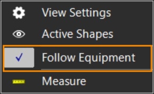
If the tick mark is visible, the Equipment is being Followed.