Crosshair
The Crosshair can be used as a 3D guidance for structure placement (X-blocks / accropodes), drains, etc.).
This bulls eye display works in combination with:
-
Targets for Vertical Drains
-
Targets for Rapid Impact Compaction

The Active Structure Target option is only available when blocks (targets) are defined in your project.
To check or change the settings for the Crosshair screen:
 Right mouse click in
Crosshair > View Settings
Right mouse click in
Crosshair > View Settings
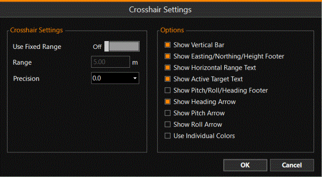
| Crosshair Settings | |
|---|---|
|
Use Fixed Range |
The Range circle will not jump, switching ranges all the time when approaching the target. |
|
Range |
When 'Use Fixed Range' was activated, enter the range here. |
|
Precision |
Use the drop down menu to select how many digits to show behind the decimal point. |
|
Options |
|
|
Show Vertical Bar |
Show a bar to the right of the crosshair/bulls eye. Here, the vertical distance to the design level is shown. This option is mainly useful for the placement of structures/blocks, not for draining or compaction works. |
|
Show Easting/Northing/Height Footer |
Show a footer below the bulls eye. (dX, dY, dZ) This is the (horizontal) distance to the target. |
|
Show Horizontal Range Text |
Show 'R = xx m' at top left. This is the range in view within the crosshair. |
|
Show Active Target Text |
Show the name of the selected target in the screen. |
|
Show Pitch/Roll/Heading Footer |
These are shown as dP, dR and dH in the footer. For use with Structures only. |
|
Show Heading Arrow |
The half arc above the crosshair shows the heading of the structure being placed. For use with Structures only. |
|
Show Pitch Arrow / Show Roll Arrow |
The bars next to and below the crosshair show the pitch and roll values of the structure being placed. For use with Structures only. |
|
Use Individual Colors |
The colors in the bars on the sides of the crosshair will differ from the tolerances. For use with Structures only. |
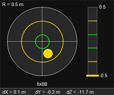
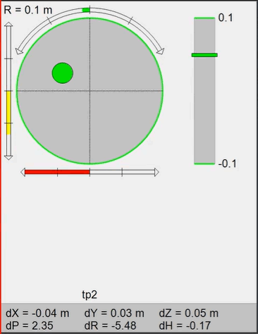
The color of the head location relative to the target location will change depending on the set tolerances.
The range circles are shown in the designated colors as well as the head of the machine.
By default they change from red to yellow to green, representing the spectrum from high to medium to low error range (which is in tolerance).
The error ranges are set in the Fix Settings.