Fix Settings
Enter how to show Fixes on screen and which data to store with each fix, plus set how to show Targets from a file as received from the surveyor.
On this page:
 MENU > Operation
Settings > General > Fix Settings or:
MENU > Operation
Settings > General > Fix Settings or:
Keyboard: F1 >
General > Fix Settings
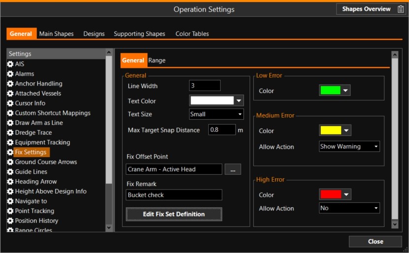
Pontoon-with-crane settings, Vibroflotation rig, or Rapid Impact Compactor
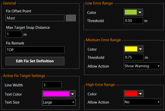
Vertical Drainage Installation Rig settings
General
|
General |
|
|---|---|
|
Line Width |
Enter how wide the circle around the target will be drawn. |
|
Text Color |
Select a color for the text (the Target ID name of the active target) in the Top View. |
|
Text Size |
Enter how large the Target ID name should be presented. |
|
The Progress Fix Set |
|
|
Fix Offset Point |
Here the location on your equipment is selected that will be used for
creating fixes. Normally you will choose the head
of your arm.
In case of a TSHD |
|
Fix Remark |
The text written at Fix Remark, will be stored with each next fix. |
|
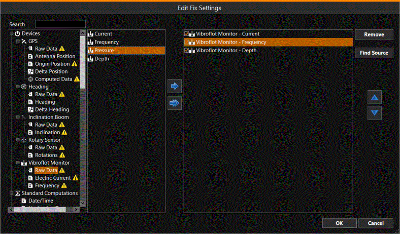
Select which other information to store along with the regular Fix info such as position, height, Fix number, date and time. Use the blue arrows to select which data to store in the Fix set.
|
|
|
(Available for Vertical Drainage Installation and Rapid Impact Compactor.) The operator will be shown which Fix Target is active by drawing a circle around it, the line width of this circle is specified here. The color of the circle is defined at High Error Range. The Target ID name of the active target will also pop up, in the color and text size as specified here. |
|
|
Low Error |
|
|
Color |
See paragraph below: Fix tolerances |
|
Medium Error |
|
|
Color |
See paragraph below: Fix tolerances |
|
Allow Action |
See paragraph below: Fix tolerances |
|
High Error |
|
|
Color |
See paragraph below: Fix tolerances |
|
Allow Action |
See paragraph below: Fix tolerances |

Fix tolerances
A Target becomes Active when your are closer than Max Target Snap Distance: the Target ID name will pop up as defined in Active Fix Target Settings.
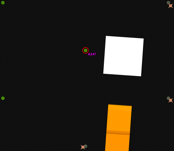
Here you are in the High Error Range, a circle will be drawn in the color defined at High Error Range (red).
Normally at High Error Range, the Allow Action is set to No and no Fix can be recorded.
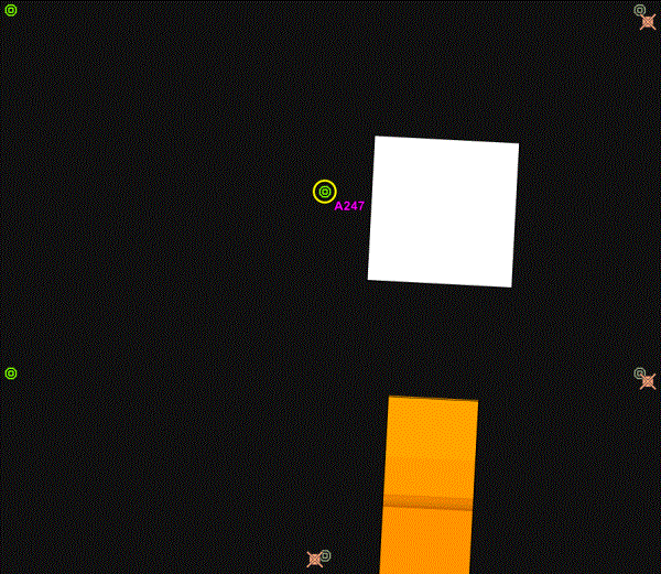
Here you are in the Medium Error Range, the color of the circle becomes the one defined at Medium Error Range (yellow).
If Allow Action is set to Show Warning, a Fix can be recorded but first a warning is given whether you are sure that you want to Fix at this position.
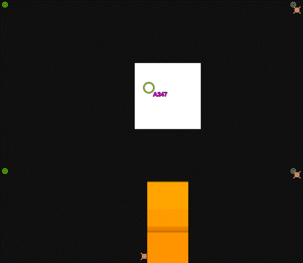
Here you are in Low Error Range, the color of the circle becomes the one defined at Low Error Range (green).
Fix Settings have no vertical tolerance settings.
Range
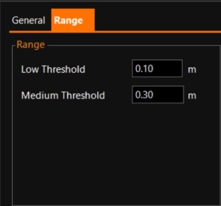
These settings are meant for use in the Crosshair View.
|
Range |
|
|---|---|
|
Low Threshold |
When you are nearing the target, the Low Threshold circle (green) will appear when you are closer than the value entered here. |
|
Medium Threshold |
When you are approaching the target, the Medium Threshold circle (yellow) will appear when you are closer than the value entered here. |