Wicks manual
Voor de Nederlandse versie zie: Wicks handleiding
2.2 Confirm tablet and computer start up
3.2 Selecting and making a project visible
4.1 Operate machine and display computer
6 Zoom in and out - shift drawing and measure
7.2 Warning message 2 - NO GPS
1 Introduction
Van Oord is an international company that generates and processes an enormous amount of data for the implementation of the projects. Because there was no program available with which Van Oord could process this data, they developed a program themselves and VOSS was created. VOSS stands for Van Oord Survey System. With this program, the Van Oord surveyors are able to create designs, 3D images and videos. But also monitoring, collecting and processing a wide variety of data are possible with VOSS.
A work-specific environment has been created for Wicks within the VOSS program. VOSS consists of 2 parts: there is a program with which the surveyors and the superintendent at the office can make designs and process data, called VOSS.NET. The other program is installed on the equipment. With this program, models can be applied and data can be logged. This part is called VOSS RT. This manual is written for Wicks for the use of VOSS RT.
2 Start up system
Before you start, the system must be installed. The following describes how to start up the system.
2.1 Switch on the GPS system
A cabinet is installed on each
machine, that controls the GPS Global Positioning System is a space-based satellite navigation system that provides location and time information in all weather, anywhere on or near the Earth, where there is an unobstructed line of sight to four or more GPS satellites. It is maintained by the United States government and is freely accessible to anyone with a GPS reciever. data. This cabinet is mounted behind the
operator's seat or behind the cabin. A green push button is mounted on
this cabinet (Fig. 1) which must be switched on. As soon as the cabinet
is switched on, the button will light up green. A switch (Fig. 2) is also
mounted on the cabinet, which must also be switched on so that the antenna
(s) and bulbs are raised.
Global Positioning System is a space-based satellite navigation system that provides location and time information in all weather, anywhere on or near the Earth, where there is an unobstructed line of sight to four or more GPS satellites. It is maintained by the United States government and is freely accessible to anyone with a GPS reciever. data. This cabinet is mounted behind the
operator's seat or behind the cabin. A green push button is mounted on
this cabinet (Fig. 1) which must be switched on. As soon as the cabinet
is switched on, the button will light up green. A switch (Fig. 2) is also
mounted on the cabinet, which must also be switched on so that the antenna
(s) and bulbs are raised.
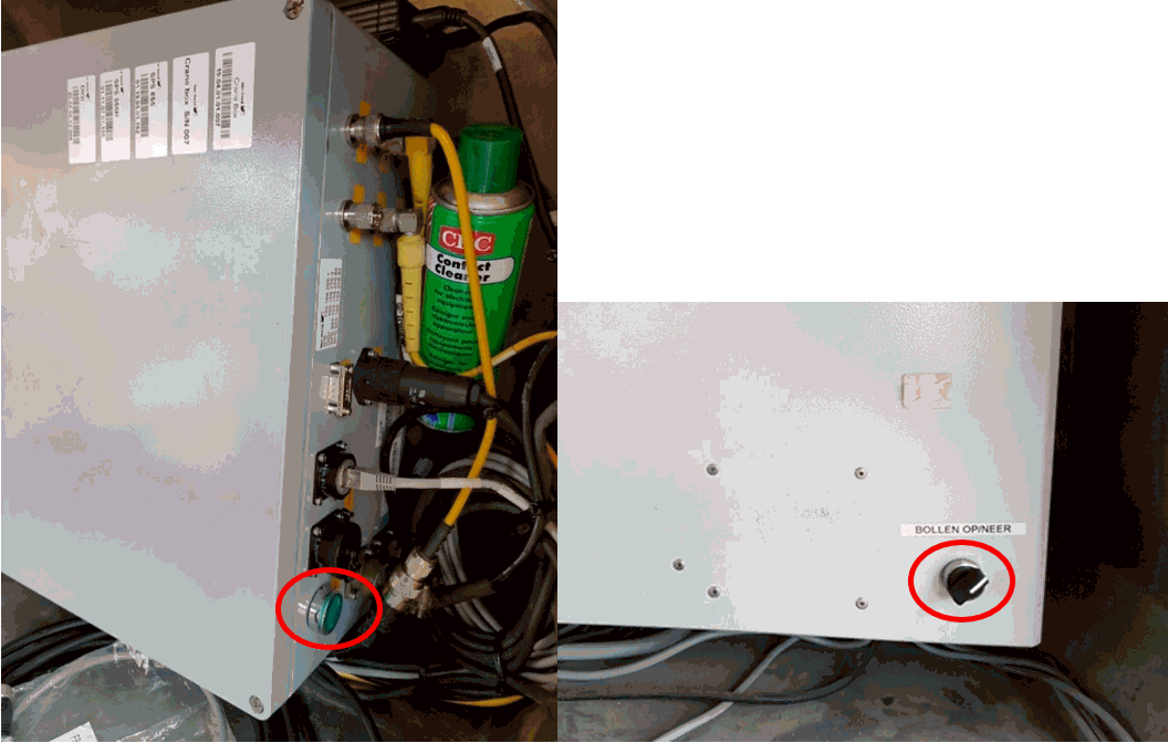
Fig. 1 Fig. 2
2.2 Confirm tablet and computer start up
Each machine has its own tablet that is adjusted to the settings of the relevant crane. These tablets are handed out to the assigned operators.
Attach
Action to include files from a Geodetic Region to your Project. the
tablet to the Docking Station and lock it with the clampsAttach the keyboard via the USB port
Press the start button on the computer
Depending on the signal strength, it may take a while for the computer to start up and connect to the Internet (Fig. 3).
2.3 Start up VOSS RT
When the computer has started up, you can check the internet connection using the icon below (Fig. 3). If a yellow triangle is visible on this icon, there is no connection to the internet (yet). If the icon indicates that it is connected to the internet, the VOSS RT program can be started. To do this, double-click the program icon on the desktop (Fig. 4.)
Pay attention! Always use the latest version of VOSS RT. You can check this with the version number (Fig. 4). The following screen will now appear on the desktop (Fig. 5). Under "Password" enter nothing and immediately click OK. The program is now started and ready to load files.

Fig. 3
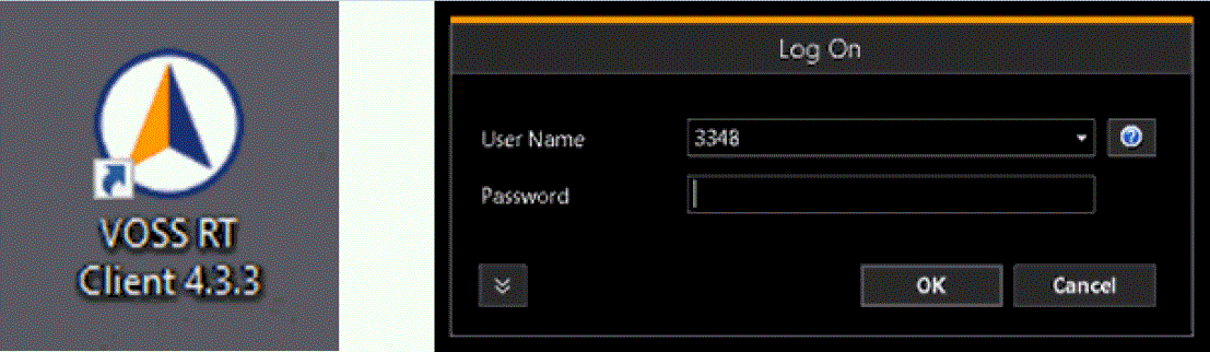
Fig. 4 Fig. 5
3 Vnar file
When a project was successfully tendered, the client will provide various files that the responsible superintendent or surveyor can use to make a design. This design is compressed together with additional data into a so-called Vnar file.
This may contain the following information:
Polygon
Plane figures that are bounded by a closed path.
Set (area(s) within which you must work)AutoCad drawings (e.g. a design drawing from the customer or a KLIC file)
Grid Model
A type of DTM that is made manageable through sampling measured points into a regularly spaced raster, allowing fast and conditional access. Considered to be a secondary data set; since no original points are kept..
(design depth minus ground level)Tin Model (design depth minus ground level)
3.1 Loading a Vnar file
When the design is ready, it can be uploaded in the computer by using a USB stick or via ISL Light on the tablet.
After starting VOSS RT, the file can be loaded as follows:
Go to Menu and select “Import package” (Fig. 6)
Select the correct Vnar, or search for the file by name and click on “Open”
Select all lines that appear under the heading "Description" and click on OK (Fig. 7)
The file is now loaded into the computer.
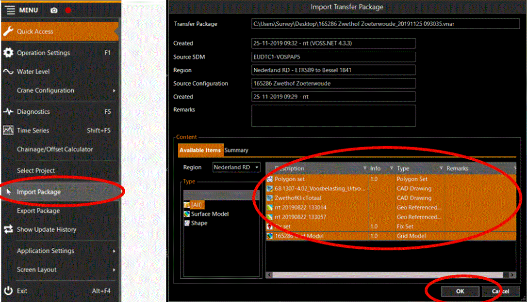
Fig. 6 Fig. 7
3.2 Selecting and making a project visible
After the file is loaded, the correct project is selected to make the imported file visible:
Go to "Menu" and click on "Select Project
An area of work that is defined and described by its tasks and/or its data sets. A project is an integrated part of any one (1) Geodetical Region." and select the correct project (Fig. 8 and
9)Go to "Menu" and click on "Operation Settings" (Fig. 10)
Select “Main Data” and click on the three dots in the bottom line (Fig. 11)
Select the correct Fix Set and click OK
Go to "Menu", click "Operation Settings", select "Design" and click "Add"(Fig. 12) and select “Surface Model
A special type of shape. It is a digital representation of a 3D surface. The used types of Surface models are: Grid Model / Point Cloud / TIN Model / Soil Layer.” (Fig. 13).
Click on the three dots and select the correct model, then click on “Select”.
Then click on the pen icon below the three dots (Fig. 14)Go to "Menu", "Operation Settings", "Supporting Data" and click on "Add" and then on "Shapes
A geometric entity or a collection of such entities. Each entity is described by basic geometry such as a point, a line or an arc. Examples of shapes are: Route, Centerline, Waypoints, Fix Set, Dump Boxes, Progress Grid Model, Designs, etc." (Fig. 15)In this window you can add KLIC deliveries, AutoCad designs and Polygons, by selecting the relevant line (s) and then clicking on “Add” (Fig. 16)
In this window, select NO Fix Set (s) unless specified by the surveyor or superintendent.
The project has now been loaded and is displayed on the screen. If desired, the color of the Fix points can be changed and the number display of the points can be turned off as follows:Go to "Menu", "Project Settings", "Main Shapes", click on the key behind Fix Set (Fig. 17)
In the “Targets” pane click on the orange bar to turn off the numbering of the design points and on the orange bar in the “Fix Points” pane to turn off the numbering at the fix points (Fig. 18)
To change the color of the design points and / or fix points, in both windows “Target” or “Fix Point
A point consists of an Easting, Northing and Elevation.”, a
color of your choice can be set by clicking on the triangle behind the
colored bars (Fig. 19)If no Vnar file from the bottom model has been imported, but a NAP depth is known, this can be set manually. See later in this manual.
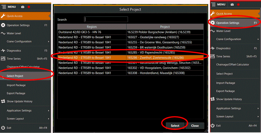
Fig. 8 Fig. 9 Fig. 10
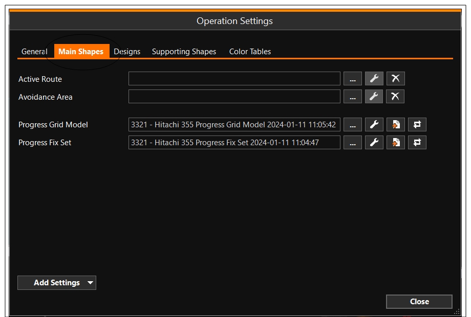
Fig. 11
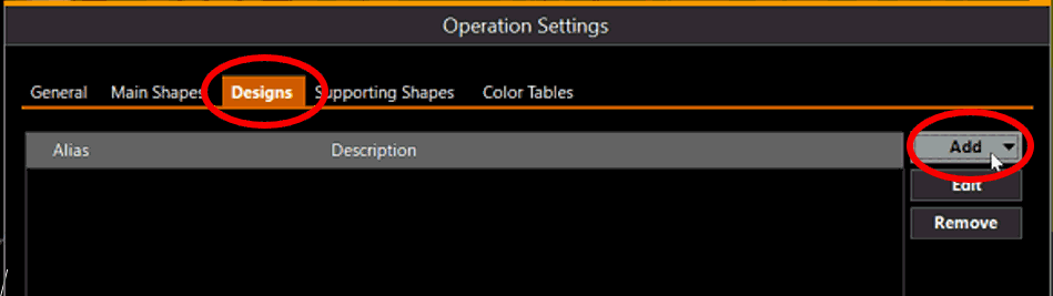
Fig. 12
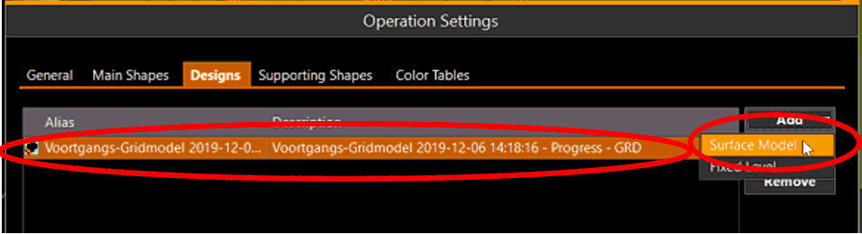
Fig. 13
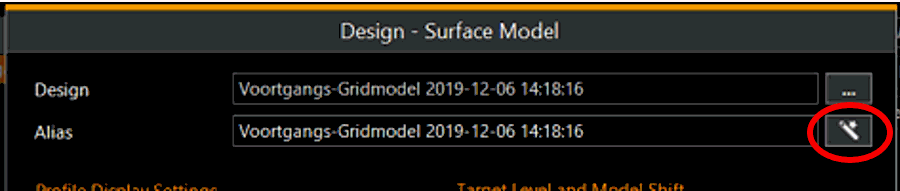
Fig. 14
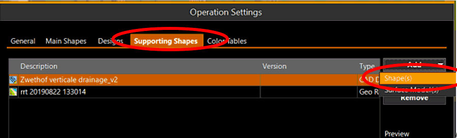
Fig. 15
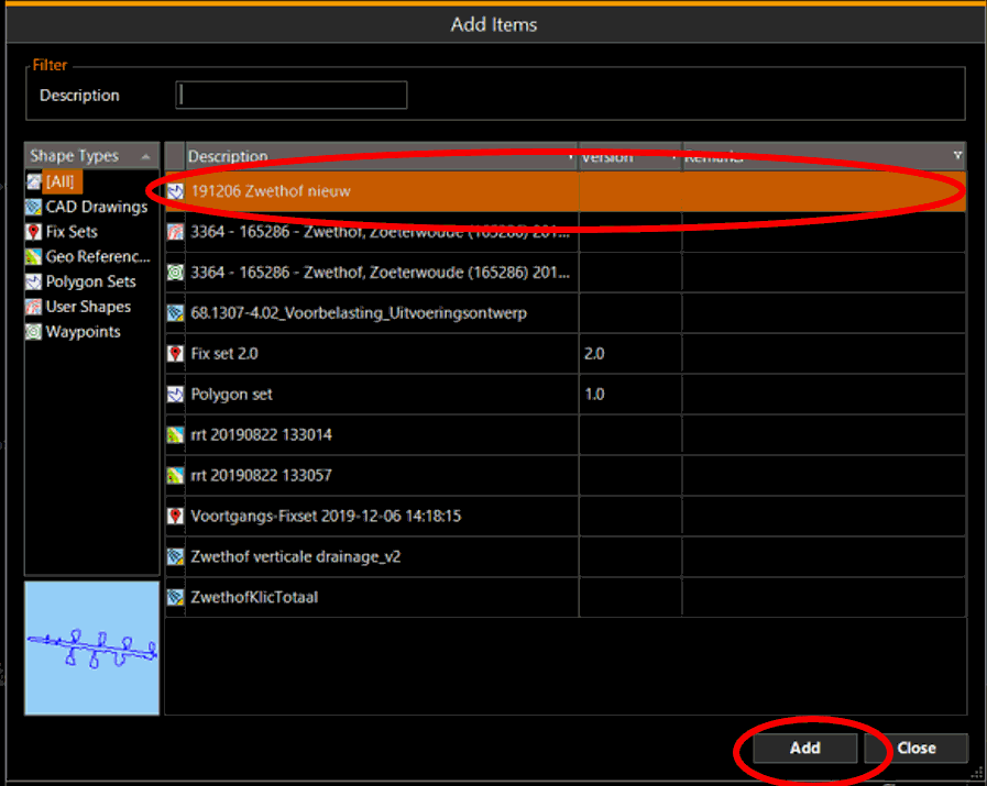
Fig. 16
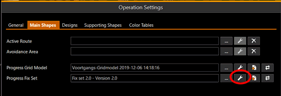
Fig. 17
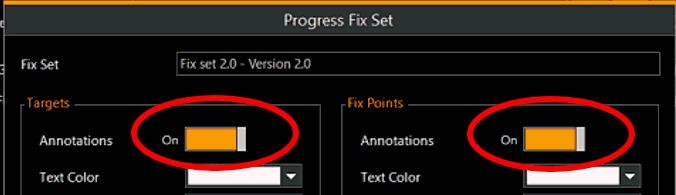
Fig. 18
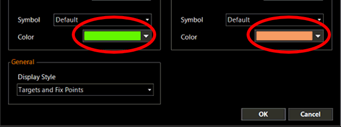
Fig. 19
4 Working with VOSS RT
When the Vnar file has been imported and the required files have been selected, the program is ready for use. Because the crane is connected to the GPS system, all movements of the crane are visible on the computer screen.
4.1 Operate machine and display computer
The operator can now move the
crane and mast to the working position and start work. While the machine
is being moved, the drawing will turn and the crane will remain centrally
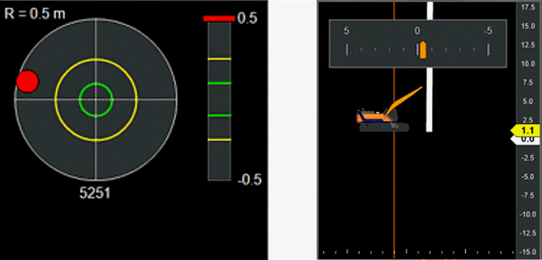
on the screen. A "Bulls Eye" is projected at the bottom left
of the screen (Fig. 20). This allows the mandrel to be positioned exactly
above a design installation point. At the bottom of the screen, the vertical
position of the mast is projected in the middle (Fig. 21). The position
of the machine / working platform relative to the NAP or any set NAP depth
(TIN Triangulated Irregular Network - a vector based data structure that describes a surface, made up of irregularly distributed 3D nodes that define constraints., GRID model or Fixed Level) can also be seen here.
If the selected depth falls outside the range of the window, this can be adjusted by clicking on the “Side View” (Fig. 21) with the mouse. Then press the "X" key (zoom out) or "Z" key (zoom in) on the keyboard. This causes the projected depth on the right-hand side of the screen to zoom in or out, so that the selected level becomes visible or disappears outside the screen.
During installation, the screen can be used to see whether the mandrel has reached the pre-set NAP depth (in case set). If this is not the case, the operator can, if desired, adjust the input depth on the kubler. At the bottom right of the screen you can read the number of fixed points, the current insertion depth, the mandrel depth relative to NAP, the total drain length and the total number of drains (Fig. 22).
Fiig. 20 Fig. 21
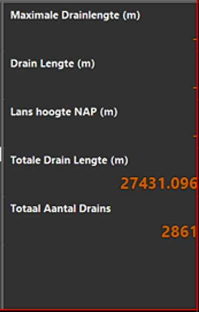
Fig. 22
4.2 Operating Computer
4.2.1 Set mandrel length
Daily, but also after the mandrel has been shortened and if a mandrel head has been changed, a calibration must be carried out. Before this can be done, the mandrel must be pulled up to the top stop, after which the “Reset Mandrel Height” button (Fig. 23) at the top of the screen, and then “OK” can be clicked. The mandrel length is now reset.
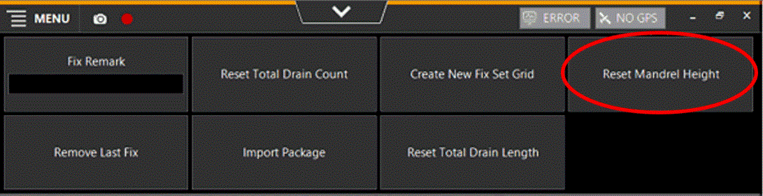
Fig. 23
4.2.2 Remove Last Fix
Sometimes it happens
that a drain does not reach the required depth and it is desirable to
remove this "waste" drain. This can be done with the help of
the “Remove Last Fix” button.
Depending on the number of clicks on this
button, the last fixed drains will be removed from the list (Fig. 24).
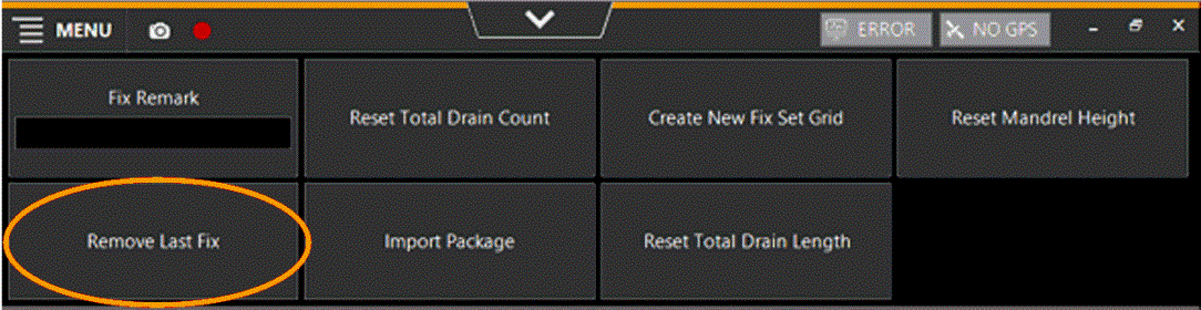
Fig. 24
4.2.3 Reset Counter
If desired, the counter for the next day can be set to zero by resetting the total number of drains and drain length (Fig. 22).
This is possible with the buttons at the top of the screen (Fig. 25).
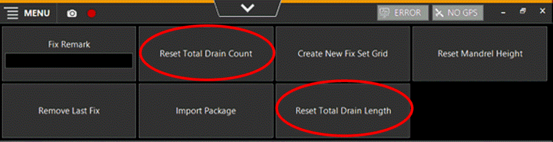
Fig. 25
4.2.4 Create Prup file
The computer logs the data per day (from 00:00 to 23:59) in the selected Fix Set(s). If several fix sets were worked on on the same day and the data had to be sent at the end of the day, then a “Prup file” must be created per fix set.
Create the description of a Prup file below:
Go to "Menu", select "Export Package" (or click on this button at the top of the screen)
In the Progress Type window, select “Progress Fix Set” (Fig. 26)
Click after the date on the triangle to select the desired date (Fig. 27)
Click on the dots after the line (Fig. 28) to select the correct file location and click on “Create”. The created file can be found in the selected folder or location.
Now the GMail account can be opened on the desktop and the Prup file can be uploaded and sent.
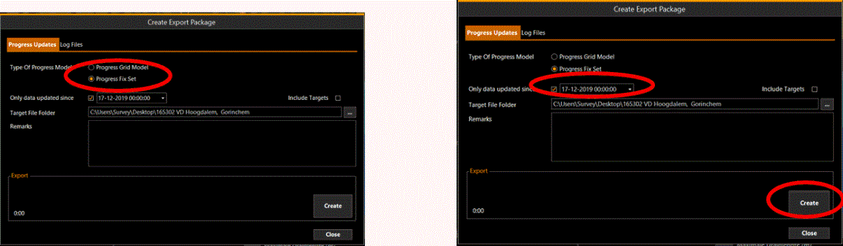
Fig. 26 Fig. 27
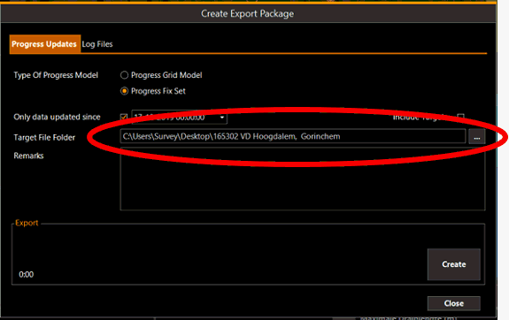
Fig. 28
4.2.5 Fix comments
Sometimes it is desirable to place a comment at certain fix points, for example to distinguish a certain area from the rest. This can be done by writing a short name, letter or number at the top of the screen in the “Fix Remark” button (Fig. 29). This comment is included in the logging and is read when processing the data.
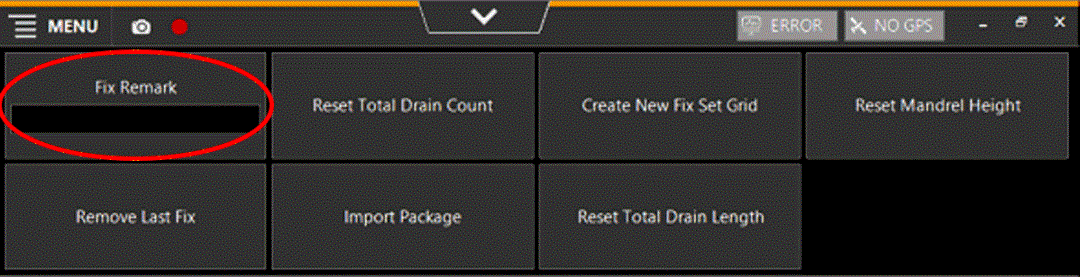
Fig. 29
4.2.6 Manually adjust NAP depth
As stated in 2.2, an NAP depth can also be set manually with the following steps:
Go to "Menu", "Operation Settings", "Designs", "Add" and then select "Fixed Level" (Fig. 30)
Note the NAP depth in the top line. Always with a - (minus sign) before the number! E.g. with installs up to 9 meters min NAP; -9.00 (Fig. 31)
Then click on the magic wand in the line below it (Fig. 32) to name the created level and then click on "OK"
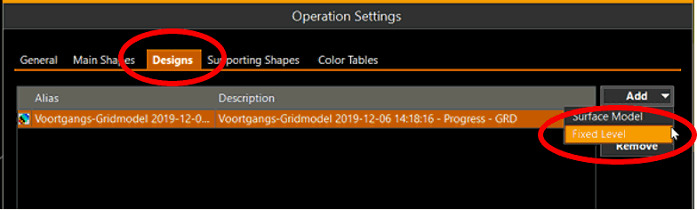
Fig. 30
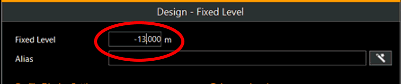
Fig. 31
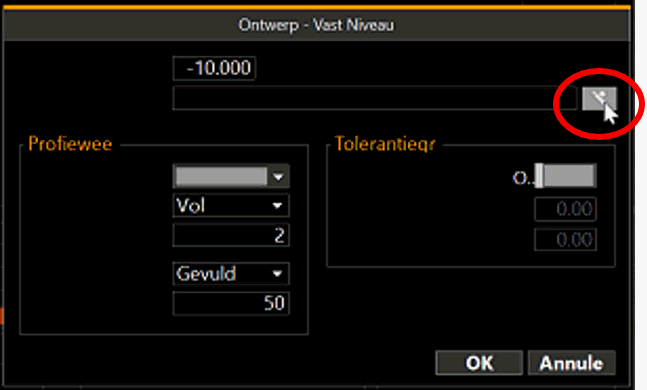
Fig. 32
5 Preferred settings
If desired, preference settings can be specified. The following describes how to enter preferred settings.
5.1 Language Setting
During the design of the program, it was decided to make three languages available: English, Dutch and Portuguese.
The language can be selected as follows:
Go to "Menu" and select "Application Settings" and click on the arrow behind "Select Language" (Fig. 33)
Select one of the three desired languages and click on "Menu" again
The desired language is now set.
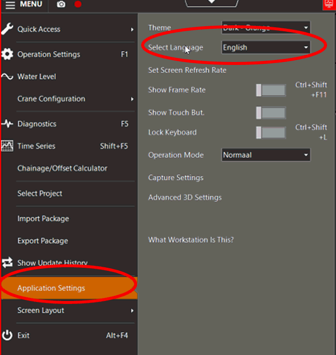
Fig. 33
5.2 Night Mode
If you need to work with little or no light, you can opt for night mode. The screen then becomes softer and more pleasing to the eyes.
You can choose this setting as follows:
Go to "Menu" and select "Quick Access" (Fig. 34)
Click on the bar behind “Night Mode” (Fig. 35)
The desired mode is now set.
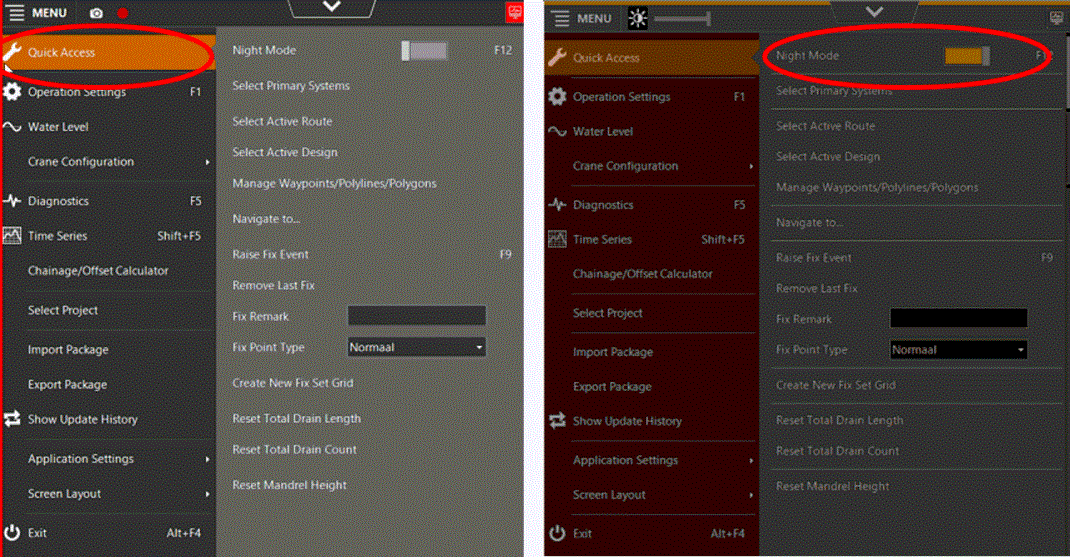
Fig. 34 Fig. 35
6 Zoom in and out, shift drawing and measure
In the start screen of VOSS RT you can zoom in and out on the design. It is also possible to perform linear (trajectory) measurements and to move the drawing across the screen.
6.1 Zooming in and out
Zooming in and out of the design in the home screen works as follows:
Take the keyboard in your hand
Click on the design in the VOSS start screen with the left mouse button
Press the “Z” key, the screen will zoom in
Press the "X" button, the screen will zoom out
6.2 Shifting the drawing
If it is desired to view a different part of the work site than where the machine is currently located, the drawing of the work site can be moved across the screen without having to zoom out.
This goes as follows:
Take the keyboard in your hand
Click on the design in the VOSS start screen with the right mouse button
Then click on "Follow Rig" (Fig. 36)
By moving the mouse over the screen and clicking, the drawing will move across the screen
Pay attention! During the execution of the work, "Follow Rig" must be switched on, otherwise the design will not move with the machine.
By following steps 1 to 4 above again, the tracking of the machine is switched on again.
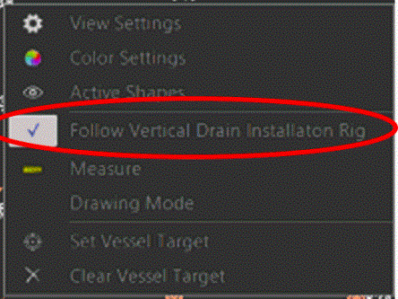
Fig. 36
6.3 Measuring in the design
To perform measurements in the design, it is advisable to first follow the steps from 6.2 before starting a measurement.
Take the keyboard in your hand
Click on the design in the VOSS start screen with the right mouse button
Select “Measure” in the screen (Fig. 37)
Move the arrow with the mouse to the starting point of the measurement and click the left mouse button
Move the arrow with the mouse to the end point of the measurement and click the left mouse button again
The distance can now be read in the screen (Fig. 38)
If you want to measure a trajectory, "Use Path" can be checked (Fig. 39). Multiple lines can now be drawn in one measurement (Fig. 40)
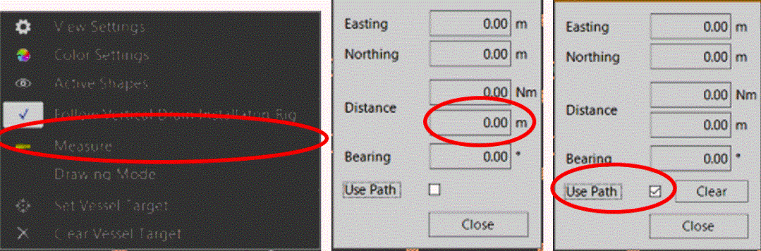
Fig. 37 Fig. 38 Fig. 39
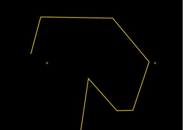
Fig. 40
7 Error messages
Error messages may occur. This can be a serious problem in some cases. In practice, this usually turns out to be small problems that are easy to solve, sometimes by the operator himself and otherwise by the superintendent or surveyor. The agreement is that in the event of malfunctions, these must be reported to the relevant superintendent at all times, so that he can, if he deems it necessary, communicate this with the survey department. Below some examples of malfunctions are given with an indication of the minimum action that is expected of the operator.
As long as there is an error message on the screen, you cannot and should not start and/or continue working!
7.1 Warning message 1 (“ERROR”)
In nine out of ten cases the error message in (Fig. 41) means that there is a connection problem in the cabling between the boom of the crane and the measuring wheel on the winch.
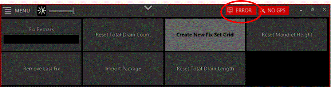
Fig. 41
Always first check whether the plugs are tightly fitted
Shut down the computer completely and restart it
Check whether cables and plugs are damaged
If these steps do not solve the problem, contact the respective superintendent and/or surveyor.
7.2 Warning message 2 ("NO GPS”)
If the error message 'No GPS' appears (Fig. 42), it is usually because no internet connection has been established or because the connection dropped.
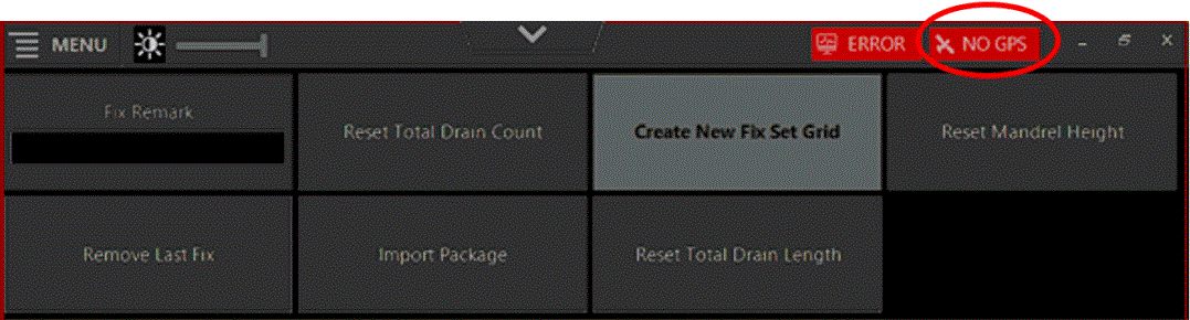
Fig. 42
Check whether the green button on the cabinet behind the seat or cabin is switched on
Check whether the bulbs and the antennas are attached and connected
Check if the plugs of the antennas and bulbs are properly connected. If necessary, spray them with contact spray
Check on your phone if you have an internet connection
Shut down the computer completely and restart it. Check if the icon on the desktop (Fig. 3) indicates connection
If these steps do not solve the problem, contact the respective superintendent and/or surveyor.